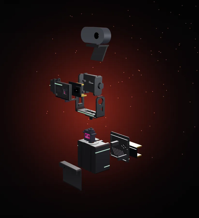
What to buy
Two ESP32 boards, two servos, a handful of wires and one lever connector. Total about $22 (AliExpress item prices before shipping, checked 18 Nov 2026). Plus a 3D printer that handles PETG and the webcam you already own.
| Part | Qty | $ | Where |
|---|---|---|---|
| ESP32 DevKit (ESP32-WROOM-32, CP2102)Main board: servo control and USB power | 1 | 4.40 | AliExpress ↗ |
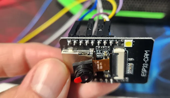
| ESP32-CAM AI-Thinker + OV2640Tracking eye: on-device face detection | 1 | 6.40 | AliExpress ↗ |
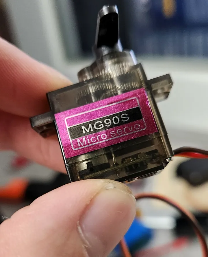
| MG90S metal-gear micro servo (pack of 2)Pan and tilt | 2 | 6.15 | AliExpress ↗ |
| Dupont jumpers 20 cm (F-F + M-F, 40 each)4 to the camera, 2 per servo | 1 | 3.20 | AliExpress ↗ |
| WAGO-type 3-way lever connectorSplits USB 5 V to both servos (sold in packs of 10, ≈$1.9) | 1 | 0.20 | AliExpress ↗ |
| PETG filament, 134 g of a 1 kg spoolWhole kit, one plate, no supports | 1 | 2.00 | AliExpress ↗ |
| Screws M2.5-M3 x 8-10 mmPlus the screws from the servo bags | 4 | — | — |
| Total before shipping | ≈22 |
Print the parts
All parts are already oriented in the files, so you never need supports. Print the fit-test plate first (about 1 h 46 min, 36 g): it checks the laptop-lid clip, the webcam rib on the head and the camera mask.
| Setting | Value |
|---|---|
| Material | PETG, any colour (black for the look) |
| Base profile | 0.20 mm Standard (Bambu P1S / X1C) |
| Walls / infill | 4 walls, 20 % gyroid |
| Nozzle | 245 °C, first layer 250 °C |
| Plate | Textured PEI, 4 mm brim, elephant foot 0.15 mm |
| Supports | None. Every part is already oriented. |
| Time / weight | 5 h 16 min, 134 g for the full kit |
Parts and orientation
| Part | Lies on the bed | Note |
|---|---|---|
| Housinghousing.stl | Front wall down | Holds the main ESP32, the pan servo and the WAGO. Rails for the lid clip print on the bed. |
| Rear covercover.stl | Flat | Posts hold the ESP32 and the servo in place. |
| Laptop lid cliplid_clip.stl | Standing on its end | Hook profile lies in the layer plane, so it is strong. 7.8 mm slot for a 7.3 mm lid. |
| Yoke (pan)yoke.stl | On its back | Uprights are strong along the layers. |
| Head (tilt)head.stl | Rib down | The pivot trunnion sits on its flat face, so it prints round. |
| Camera maskshroud.stl | Face down | Front face gets the bed texture and the engraved reticle. |
| Tilt servo capservo_cap.stl | Bottom down | Press fit, optional. Wire slots on both ends. |
| Desk stand (optional)desk_foot.stl | Flat | Turns the laptop mount into a desk unit. |
| Shims 0.2 / 0.4 / 0.6 mmshim_02.stl / shim_04.stl / shim_06.stl | Flat | Only if the yoke has vertical play. |
Neon lines: press any 1.75 mm filament into the 1.8 × 1.4 mm grooves after printing. The print itself stays single colour, no AMS needed.
Flash the firmware
Wire the four camera wires first (see Wiring): the camera is flashed through the main board. Curious how it works inside? Read the firmware explained. Two sketches: FT_main for the main ESP32 and FT_cam for the ESP32-CAM. You can use Arduino IDE (board “ESP32 Dev Module”; for the camera set PSRAM: Enabled and Partition Scheme: Huge APP) or the command line:
# 1. Toolchain (once). Use core 2.0.17: the face detector headers were removed in 3.x
arduino-cli core update-index --additional-urls https://espressif.github.io/arduino-esp32/package_esp32_index.json
arduino-cli core install esp32:esp32@2.0.17 --additional-urls https://espressif.github.io/arduino-esp32/package_esp32_index.json

# 2. Main board (plug in only the main ESP32)
arduino-cli compile --fqbn esp32:esp32:esp32 firmware/FT_main
arduino-cli upload  --fqbn esp32:esp32:esp32 -p <PORT> firmware/FT_main   # Windows: COM4, macOS: /dev/cu.usbserial-*, Linux: /dev/ttyUSB0

# 3. Camera firmware
arduino-cli compile --fqbn esp32:esp32:esp32:PSRAM=enabled,PartitionScheme=huge_app \
  --output-dir build/cam firmware/FT_cam
ESP32-CAM without a programmer
The ESP32-CAM has no USB port. Instead of an extra adapter, the main board becomes a USB-to-serial bridge on command, while the camera stays wired exactly as in the final build.
# 4. Flash the ESP32-CAM through the main board (no programmer)
#    a) jumper: camera IO0 -> GND (NOT to the main board IO0), press RST on the camera
#    b) switch the main board to bridge mode: send "bridge" in a 921600 serial monitor, close it
#    c) write the camera at 115200:
esptool.py --chip esp32 --port <PORT> --baud 115200 --before no_reset --after no_reset write_flash \
  0x1000 build/cam/FT_cam.ino.bootloader.bin  0x8000 build/cam/FT_cam.ino.partitions.bin \
  0xe000 boot_app0.bin  0x10000 build/cam/FT_cam.ino.bin
#    (boot_app0.bin ships with the core: .../esp32/hardware/esp32/2.0.17/tools/partitions/boot_app0.bin)
#    d) remove the jumper, press RST. The main board leaves bridge mode by itself after 10 idle minutes,
#       or immediately when it receives the text ~~FT-EXIT~~ at 115200. Windows users: tools/flash_cam_bridge.ps1 does all of this.
Wiring
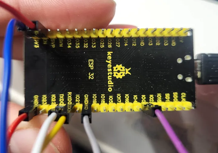
Four wires to the camera, all on one pin row of the ESP32-CAM (3V3, IO16, IO0, GND, VCC, U0R, U0T, GND). In the head this row ends up at the bottom and the wires leave backwards under the rib.
| ESP32-CAM | Main ESP32 | Wire |
|---|---|---|
| 3V3 | 3V3 | Dupont F-F 20 cm |
| GND (next to IO0) | GND | F-F |
| U0T | IO16 | F-F |
| U0R | IO17 | F-F |
Servos and power
| Servo | Orange (signal) | Brown (GND) | Red (+5 V) |
|---|---|---|---|
| Pan (in housing) | IO18 | GND | WAGO |
| Tilt (on yoke) | IO19 | GND | WAGO |
- 5 V comes from USB: the main board’s 5V pin goes to the WAGO, together with both red servo leads. Pull the red lead out of the servo plug (lift the tab with a needle) or cut and strip it.
- Signal and ground: male-to-female Dupont jumpers, male end into the servo plug, female end onto the board pin.
- The camera runs from 3V3, its 5 V pin stays empty. That works with a healthy regulator and with a dead one.
- Route the tilt servo lead and the four camera wires through the deck port (rear left) and leave a 6-7 cm loop so the head can turn freely.
Assembly
Hardware: 2 screws from the servo bag for the tilt servo tabs, 1 horn screw for the pan servo, 4 self-tapping screws M2.5-M3 × 8-10 mm (2 for the cover, 2 for the camera mask) and one WAGO 221-413 or 222-413.
Flash both boards
Flash the main ESP32 over its own USB, then flash the ESP32-CAM through it (bridge mode, no extra programmer). Power the main board with servos attached: both go to centre (1500 µs). Fit the horns only on centred servos.
Pan servo into the housing
Slide the pan servo in from the back, tabs into the slots, shaft up. Its lead leaves on the shaft side and drops down into the bay.
Main ESP32 on its posts
Lay the main board on 4 posts: USB into the right-hand window, the USB edge under two hooks, pins facing back.
Yoke on the deck ring
Put the yoke on the deck ring, uprights up, square to the housing. Drop the double horn into its pocket and onto the shaft, tighten the centre screw. It must turn by hand without vertical play. If it rattles, add a 0.2 / 0.4 / 0.6 mm shim.
Head into the yoke
Press the second horn into the pocket on the right cheek of the head. Put the head trunnion into the hole of the left upright.
Tilt servo
Insert the tilt servo from outside into the right upright window, shaft into the horn, lead up. Two screws into the tabs. The head rib must stand vertical. Press the servo cap on top.
ESP32-CAM on the head
Push the 4 wires onto the lower pin row, then place the board on the 4 rib posts with the camera forward. Seen from the front the lens is on the right. The upper pin row goes into the rib slot; wires leave backwards under the rib.
Camera mask
Slide the mask up along the cheek guides until the square lens head sits in its window. Two screws from below.
Wires and power
Route the wires through the deck port (rear left), leave a 6-7 cm loop so the head turns freely. Plug them per the wiring tables, all red servo leads and the 5 V lead into the WAGO. Close the cover, 2 screws.
Lid clip
Slide the clip onto the housing from below until it stops. The weight of the device locks it.
Neon (optional)
Press any 1.75 mm filament into the 1.8 x 1.4 mm grooves for the neon lines. A drop of glue if loose. The print itself stays single colour.
Mount and plug in
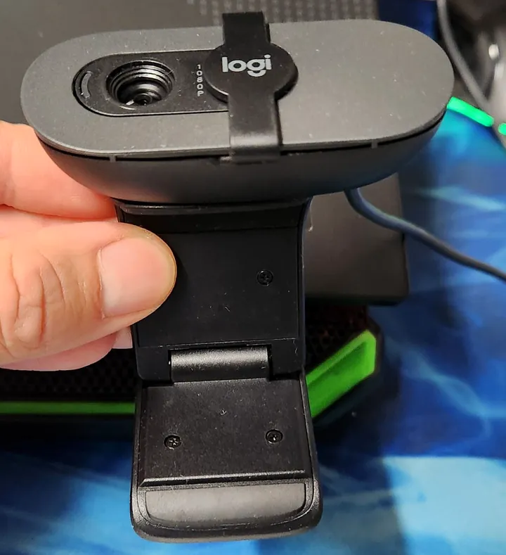
Hang it on the laptop lid, clip your webcam onto the head rib like onto a monitor edge, plug in both USB cables. Sit in front of it: the head finds your face and centres it.
First run and troubleshooting
Open any serial monitor on the main board at 921 600 baud and type status. LOCK means it sees your face, SEARCH means it is looking, NOLINK means no data from the camera.
| Symptom | Fix |
|---|---|
| NOLINK in the monitor | No data from the ESP32-CAM. Check the 4 camera wires: U0T to IO16, U0R to IO17. |
| “frame timeout” from the camera | The sensor stopped delivering frames. Unplug USB for 5 s. If it repeats, reseat the camera ribbon: lift the latch, push the ribbon fully in, close the latch. |
| A servo runs away from the face | Type flip pan or flip tilt, then save. |
| Face is off-centre in your webcam | The webcam sits beside the tracking camera. Shift the aim: set aimx -4.8 / set aimy 4 (degrees), then save. |
| USB drops while servos move | The laptop port sags. Add a 470-1000 µF capacitor across 5 V / GND, or use a powered hub. |
| Moves feel too soft or too sharp | set smooth 500 sets the eased move time in ms (0 = direct). |
Serial commands
| Command | What it does |
|---|---|
status | Live state: LOCK / SEARCH / NOLINK, angles, fps |
track 0 / 1 | Tracking off / on |
center | Both servos to the middle (for fitting the horns) |
pan <deg> / tilt <deg> | Manual move |
flip pan | tilt | Reverse an axis |
set kp | dead | speed | smooth | aimx | aimy … | Tuning; show lists everything |
cam <rot | score | in | roi | perf …> | ESP32-CAM settings, passed through |
bridge | USB ↔ camera link for flashing the ESP32-CAM |
log | Last 256 camera reports with servo angles |
save | Store settings in flash |
Settings that worked on the reference build: kp 0.85, dead zone 1.5°, speed 180°/s, lag 120 ms, smooth 500 ms, tilt min −65°. Camera: in 72, roi 2.4, score 0.2, xclk 20 MHz.
Files
Print plates (Bambu Studio 3MF)
Full kit on one plate + fit-test plate, sliced for P1S / X1C PETG.
STL files
Every part already in print orientation. Any slicer.
STEP CAD
Parts and full assembly for Fusion, FreeCAD, SolidWorks, Onshape.
Firmware
ESP32 main board + ESP32-CAM sketches and flashing scripts.
Licence: firmware and code MIT; models, print files and documentation CC BY 4.0. Credit “OKO-1 by SDTech / Serhii Dovhyi” when you share or sell a derivative.